Process control precision isn't just a goal; it's a critical operational parameter. Whether you’re managing temperature, pressure, flow, or level, the accuracy of your system hinges on a single, often-overlooked component: the control valve positioner.
When your control valves aren't responsive, your entire process suffers from reduced efficiency, increased waste, and potential safety risks. The solution often isn't replacing the expensive control valve, but rather, performing a precise calibration on the positioner.
Below, we provide a definitive, technical guide on how to calibrate a pneumatic valve positioner, complete with a step-by-step diagram, and explain how Regent’s integrated control solutions simplify this process for you.
____________________________________________________________
Understanding the Valve Positioner Calibration Process
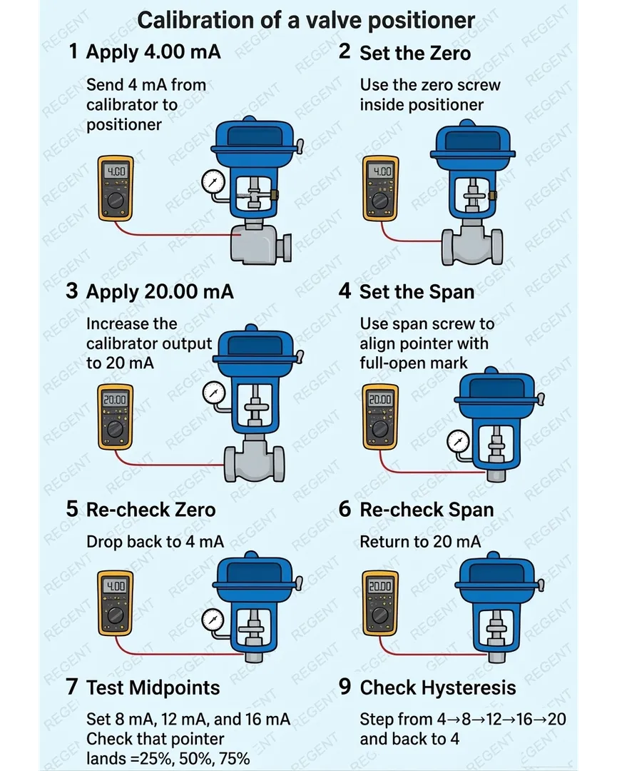
The diagram below provides a visual walkthrough of a standard calibration procedure for a current-to-pneumatic (I/P) valve positioner, which operates on a standard 4-20mA control signal.
This procedure is essential for converting the precise electric current output of your Distributed Control System (DCS) or PLC into an accurate physical position of the valve stem. Let's break down the key technical stages.
Section 1: Establishing the Initial State and Maximum Signal (Input)
Step 1: Apply 4.00 mA The process begins with a base input. Using a reliable calibrator (like the yellow handheld multimeter shown), send exactly 4.00mA. This simulates the 'fully closed' or zero signal from your controller. Crucially, your pressure gauge and positioner should reflect this initial state.
Step 3: Apply 20.00 mA Next, we determine the maximum range of the signal. Increase the input signal to exactly 20.00mA. This represents the 'fully open' signal. Observe how the pressure gauge and valve position change dramatically.
Section 2: Zero and Span Adjustment (The Core)
Step 2: Set the Zero With the input back at 4.00mA, locate and adjust the zero adjustment screw inside the positioner. The goal is to set the physical zero point of the valve (fully closed) while sending the minimum current. Make incremental adjustments until the valve pointer is perfectly aligned with the zero mark. This ensures the valve is truly closed when commanded.
Step 4: Set the Span With the input at 20.00mA, locate and adjust the span adjustment screw. The goal is to set the physical maximum point of the valve (fully open) for the full 20mA current. Adjust the screw until the valve pointer perfectly aligns with the full-open mark. This adjustment must be precise to avoid overstressing the actuator or failing to reach full flow.
Section 3: The Verification Loop
Step 5: Re-check Zero Calibration is an iterative process. Changing the span adjustment can affect the zero point, and vice-versa. Immediately drop the signal back to 4.00mA. Verify that the valve pointer returns precisely to zero. If not, repeat Step 2 and then Step 4. You must loop through these steps until both end points are perfect on the first try.
Step 6: Re-check Span Similarly, return the signal to 20.00mA. Confirm the valve pointer travels precisely to the full-open mark. If it's off, re-adjust the span screw (Step 4) and then immediately re-verify the zero point (Step 5).
Section 4: Advanced Performance Tests (Linearity and Dynamics)
Once your endpoints are solid, it's time to check the positioner's intermediate accuracy and dynamic response.
H2: Midpoint Verification (Linearity Check)
Step 7: Test Midpoints Setting 4mA and 20mA only calibrates the two endpoints. It doesn’t guarantee the valve responds linearly in between. Linear control is crucial for smooth process tuning. Set the calibrator to key midpoints—8mA, 12mA, and 16mA. Verify that the valve pointer lands precisely on the 25%, 50%, and 75% travel marks, respectively.
Technical Tip: If your valve is a linear-characteristic type and the pointer doesn’t land on the midpoints, the control performance will be poor, even if zero and span are correct. This can indicate a problem with the positioner's internal linkage, cam profile, or a need for a non-linear cam (for logarithmic characteristics).
H2: Check Hysteresis (Dynamic Test)
Step 9: Check Hysteresis Hysteresis is the difference in valve position when the same control signal is reached from opposite directions (e.g., reaching 12mA from 4mA vs. reaching 12mA from 20mA). It measures the friction and mechanical play in the system.
- Step up from 4mA → 8mA → 12mA → 16mA → 20mA.
- Then immediately step down in reverse back to 4mA.
- At each step, note the pointer position.
The Regent Advantage: High-quality control valve assemblies, like those provided by Regent, are designed with minimal mechanical play and low-friction packings to minimize hysteresis. Minimal hysteresis is critical for achieving a stable and repeatable process control loop.
_____________________________________________________________
Regent: Your Partner for Precise Control Valve Solutions
Understanding calibration is vital for maintenance, but avoiding problems starts with the right equipment. Regent provides integrated control valve with valve positioner solutions suitable for your specific process application.
Why partner with Regent?
- Matched Components: We don't just sell you parts; we engineer complete assemblies. We ensure the actuator, valve body material, and trim are matched not only to your process fluids and pressures but also that the positioner is selected for optimal performance in that specific assembly.
- Factory-Calibrated Precision: Our control valves can arrive pre-assembled and factory-calibrated according to your specifications, ready for immediate installation. This saves you valuable commissioning time and ensures a reliable starting point.
- Local Expertise and Support: Serving clients across Gujarat from our base in Ahmedabad, Regent offers rapid on-site support, troubleshooting, and replacement parts. Our local knowledge means we understand the unique industrial challenges of the region.
- Process Suitability: Whether you need standard pneumatic, hazardous-area certified, or high-performance digital positioners for your process application, our experts will guide you to the correct product, ensuring long-term reliability and minimal maintenance.
_____________________________________________________________
Need expert consultation on sourcing the perfect control valve with a positioner for your next project? Or struggling with calibration on existing equipment? Contact Regent today for specialized solutions and local support.
Phone: +91-9998774853 Email: sales@controlvalveregent.com
Visit: Ahmedabad, Gujarat, India
Keywords