How to Read Valve Body Markings in the Piping Industry
In the piping field, reading the data engraved on a valve body is not optional - it is a technical responsibility. Every valve carries its complete technical identity, and every engineer, supervisor, and QA/QC inspector must fully understand it before installation.
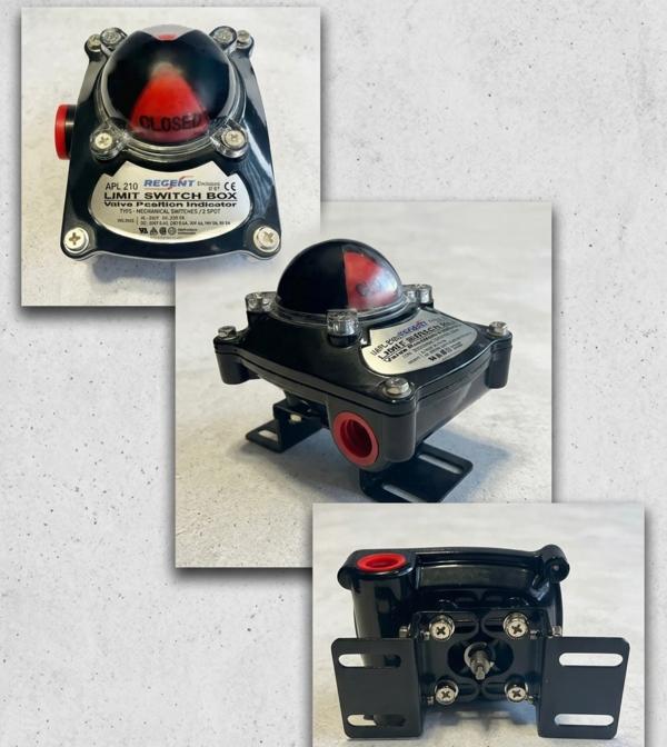
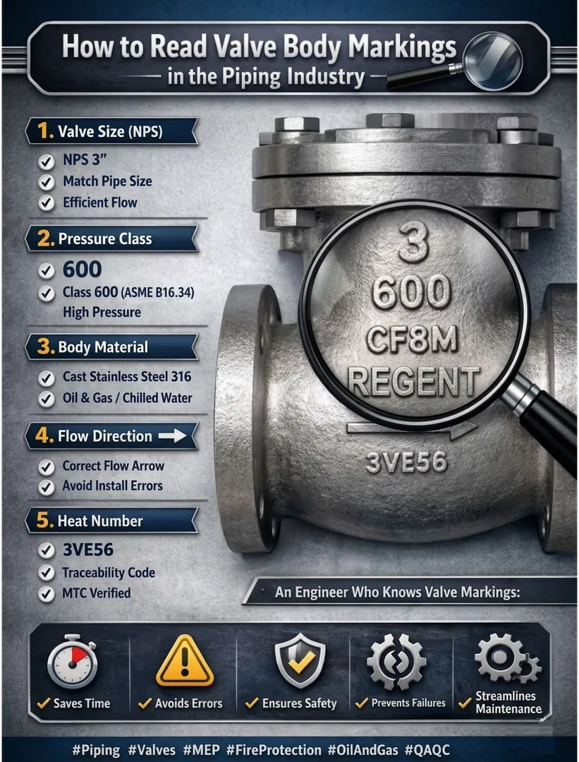
Let's take a practical example of a valve from REGENT and break down the key markings:
1. Valve Size (NPS)
Marking Example: 3
- Means NPS 3'
- Must match the pipeline size
- Prevents pressure loss
- Ensures efficient flow
Pipe dimensions follow:
ASME B36.10 (Carbon Steel)
ASME B36.19 (Stainless Steel)
2. Pressure Class
Marking Example: 600
· Class 600 according to ASME B16.34
· Higher class = higher pressure tolerance
· Based on Pressure-Temperature tables
Common Classes:
150 → Low pressure
300 - Medium pressure
600 → High pressure
900 → Very high pressure
Used widely in: Steam, Oil & Gas, Heavy industrial systems.
3.Body Material
Marking Example: CF8M
According to ASTM International - ASTM A351
CF8M = Cast Stainless Steel 316
· High corrosion resistance
· Suitable for chemical & wet environments
· Common in Oil & Gas & Chilled Water
Comparison:
CF8M → Stainless Steel
WCB → Carbon Steel
Material selection depends on: Fluid type | Temperature I Corrosion | Hygiene requirements
4. Flow Direction
Arrow on the body indicates correct flow direction.
Globe & Check valves must be installed correctly.
Wrong installation may cause: Leakage
· Performance loss
· Internal damage
· Cavitation
5. Heat Number (Traceability)
Example: 3VE56
· Track manufacturing batch
· Verify MTC
· Meet Oil & Gas QA/QC requirements
Traceability is mandatory in large EPC projects.
Before Installing Any Valve, Verify:
· Size (NPS)
· Pressure Class
· Body Material
· Flow Direction
· Manufacturer
· Material Certificate
This is a key part of Pre-Installation Inspection.
An engineer who knows how to read valve markings:
· Saves time
· Prevents installation errors
· Ensures safety
· Protects the system from failure
Keywords